Hola a todos:
En esta sesión vamos a introducir el condicional en programación, utilizar salidas y entradas analógicas.
PROYECTOS DE LA SESIÓN 2:
- Parpadeo de intensidad gradual de un LED.
- Efecto fuego con un LED.
- Cambios de color con un LED RGB.
- Sensor LDR.
- Sensor LDR y encendido de LEDs.
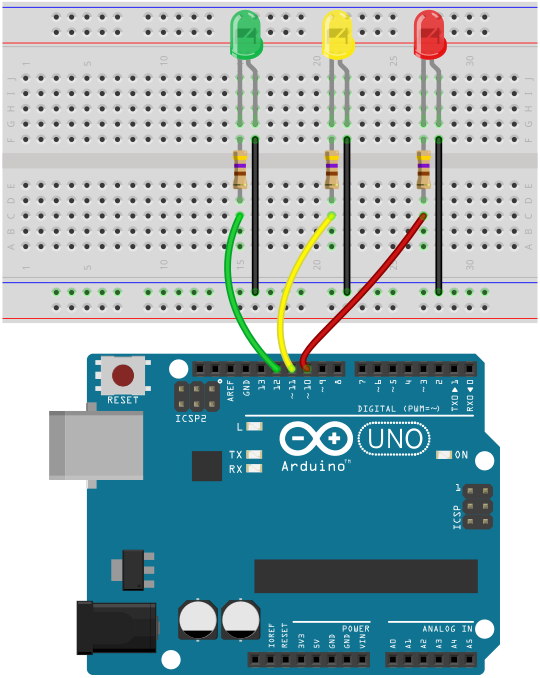
1. Parpadeo de intensidad gradual de un LED.
2. Efecto fuego con un LED.
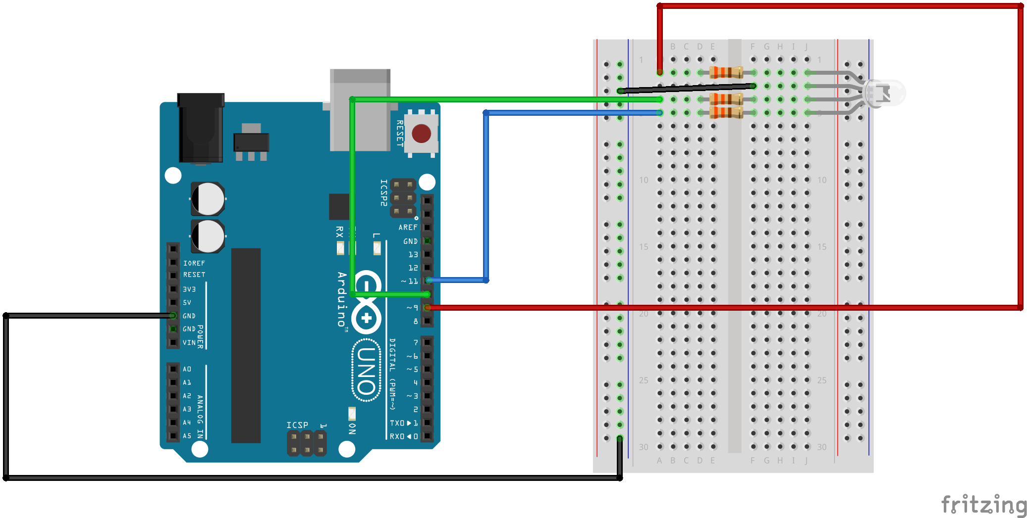
3. Cambios de color con un LED RGB.
/*
SparkFun Inventor's Kit
Example sketch 03
RGB LED
Make an RGB LED display a rainbow of colors!
Hardware connections:
An RGB LED is actually three LEDs (red, green, and blue) in
one package. When you run them at different brightnesses,
the red, green and blue mix to form new colors.
Starting at the flattened edge of the flange on the LED,
the pins are ordered RED, COMMON, GREEN, BLUE.
Connect RED to a 330 ohm resistor. Connect the other end
of the resistor to Arduino digital pin 9.
Connect COMMON pin to GND.
Connect GREEN to a 330 ohm resistor. Connect the other end
of the resistor to Arduino digital pin 10.
Connect BLUE to a 330 ohm resistor. Connect the other end
of the resistor to Arduino digital pin 11.
This sketch was written by SparkFun Electronics,
with lots of help from the Arduino community.
Visit http://learn.sparkfun.com/products/2 for SIK information.
Visit http://www.arduino.cc to learn about the Arduino.
Version 2.0 6/2012 MDG
*/
// First we'll define the pins by name to make the sketch
// easier to follow.
// Here's a new trick: putting the word "const" in front of a
// variable indicates that this is a "constant" value that will
// never change. (You don't have to do this, but if you do, the
// Arduino will give you a friendly warning if you accidentally
// try to change the value, so it's considered good form.)
const int RED_PIN = 9;
const int GREEN_PIN = 10;
const int BLUE_PIN = 11;
// This variable controls how fast we loop through the colors.
// (Try changing this to make the fading faster or slower.)
int DISPLAY_TIME = 10; // In milliseconds
void setup()
{
// Here we'll configure the Arduino pins we're using to
// drive the LED to be outputs:
pinMode(RED_PIN, OUTPUT);
pinMode(GREEN_PIN, OUTPUT);
pinMode(BLUE_PIN, OUTPUT);
}
void loop()
{
// In this sketch, we'll start writing our own functions.
// This makes the sketch easier to follow by dividing up
// the sketch into sections, and not having everything in
// setup() or loop().
// We'll show you two ways to run the RGB LED.
// The first way is to turn the individual LEDs (red, blue,
// and green) on and off in various combinations. This gives you
// a total of eight colors (if you count "black" as a color).
// We've written a function called mainColors() that steps
// through all eight of these colors. We're only "calling" the
// function here (telling it to run). The actual function code
// is further down in the sketch.
mainColors();
// The above function turns the individual LEDs full-on and
// full-off. If you want to generate more than eight colors,
// you can do so by varying the brightness of the individual
// LEDs between full-on and full-off.
// The analogWrite() function lets us do this. This function
// lets you dim a LED from full-off to full-on over 255 steps.
// We've written a function called showSpectrum() that smoothly
// steps through all the colors. Again we're just calling it
// here; the actual code is further down in this sketch.
showSpectrum();
}
// Here's the mainColors() function we've written.
// This function displays the eight "main" colors that the RGB LED
// can produce. If you'd like to use one of these colors in your
// own sketch, you cancopy and paste that section into your code.
void mainColors()
{
// Off (all LEDs off):
digitalWrite(RED_PIN, LOW);
digitalWrite(GREEN_PIN, LOW);
digitalWrite(BLUE_PIN, LOW);
delay(1000);
// Red (turn just the red LED on):
digitalWrite(RED_PIN, HIGH);
digitalWrite(GREEN_PIN, LOW);
digitalWrite(BLUE_PIN, LOW);
delay(1000);
// Green (turn just the green LED on):
digitalWrite(RED_PIN, LOW);
digitalWrite(GREEN_PIN, HIGH);
digitalWrite(BLUE_PIN, LOW);
delay(1000);
// Blue (turn just the blue LED on):
digitalWrite(RED_PIN, LOW);
digitalWrite(GREEN_PIN, LOW);
digitalWrite(BLUE_PIN, HIGH);
delay(1000);
// Yellow (turn red and green on):
digitalWrite(RED_PIN, HIGH);
digitalWrite(GREEN_PIN, HIGH);
digitalWrite(BLUE_PIN, LOW);
delay(1000);
// Cyan (turn green and blue on):
digitalWrite(RED_PIN, LOW);
digitalWrite(GREEN_PIN, HIGH);
digitalWrite(BLUE_PIN, HIGH);
delay(1000);
// Purple (turn red and blue on):
digitalWrite(RED_PIN, HIGH);
digitalWrite(GREEN_PIN, LOW);
digitalWrite(BLUE_PIN, HIGH);
delay(1000);
// White (turn all the LEDs on):
digitalWrite(RED_PIN, HIGH);
digitalWrite(GREEN_PIN, HIGH);
digitalWrite(BLUE_PIN, HIGH);
delay(1000);
}
// Below are two more functions we've written,
// showSpectrum() and showRGB().
// showRGB() displays a single color on the RGB LED.
// You call showRGB() with the number of a color you want
// to display.
// showSpectrum() steps through all the colors of the RGB LED,
// displaying a rainbow. showSpectrum() actually calls showRGB()
// over and over to do this.
// We'll often break tasks down into individual functions like
// this, which makes your sketches easier to follow, and once
// you have a handy function, you can reuse it in your other
// programs.
// showSpectrum()
// This function steps through all the colors of the RGB LED.
// It does this by stepping a variable from 0 to 768 (the total
// number of colors), and repeatedly calling showRGB() to display
// the individual colors.
// In this function, we're using a "for() loop" to step a variable
// from one value to another, and perform a set of instructions
// for each step. For() loops are a very handy way to get numbers
// to count up or down.
// Every for() loop has three statements separated by semicolons:
// 1. Something to do before starting
// 2. A test to perform; as long as it's true,
// it will keep looping
// 3. Something to do after each loop (usually
// increase a variable)
// For the for() loop below, these are the three statements:
// 1. x = 0; Before starting, make x = 0.
// 2. x < 768; While x is less than 768, run the
// following code.
// 3. x++ Putting "++" after a variable means
// "add one to it". (You can also use "x = x + 1")
// Every time you go through the loop, the statements following
// the loop (those within the brackets) will run.
// And when the test in statement 2 is finally false, the sketch
// will continue.
void showSpectrum()
{
int x; // define an integer variable called "x"
// Now we'll use a for() loop to make x count from 0 to 767
// (Note that there's no semicolon after this line!
// That's because the for() loop will repeat the next
// "statement", which in this case is everything within
// the following brackets {} )
for (x = 0; x < 768; x++)
// Each time we loop (with a new value of x), do the following:
{
showRGB(x); // Call RGBspectrum() with our new x
delay(DISPLAY_TIME); // Delay for 10 ms (1/100th of a second)
}
}
// showRGB()
// This function translates a number between 0 and 767 into a
// specific color on the RGB LED. If you have this number count
// through the whole range (0 to 767), the LED will smoothly
// change color through the entire spectrum.
// The "base" numbers are:
// 0 = pure red
// 255 = pure green
// 511 = pure blue
// 767 = pure red (again)
// Numbers between the above colors will create blends. For
// example, 640 is midway between 512 (pure blue) and 767
// (pure red). It will give you a 50/50 mix of blue and red,
// resulting in purple.
// If you count up from 0 to 767 and pass that number to this
// function, the LED will smoothly fade between all the colors.
// (Because it starts and ends on pure red, you can start over
// at 0 without any break in the spectrum).
void showRGB(int color)
{
int redIntensity;
int greenIntensity;
int blueIntensity;
// Here we'll use an "if / else" statement to determine which
// of the three (R,G,B) zones x falls into. Each of these zones
// spans 255 because analogWrite() wants a number from 0 to 255.
// In each of these zones, we'll calculate the brightness
// for each of the red, green, and blue LEDs within the RGB LED.
if (color <= 255) // zone 1
{
redIntensity = 255 - color; // red goes from on to off
greenIntensity = color; // green goes from off to on
blueIntensity = 0; // blue is always off
}
else if (color <= 511) // zone 2
{
redIntensity = 0; // red is always off
greenIntensity = 255 - (color - 256); // green on to off
blueIntensity = (color - 256); // blue off to on
}
else // color >= 512 // zone 3
{
redIntensity = (color - 512); // red off to on
greenIntensity = 0; // green is always off
blueIntensity = 255 - (color - 512); // blue on to off
}
// Now that the brightness values have been set, command the LED
// to those values
analogWrite(RED_PIN, redIntensity);
analogWrite(BLUE_PIN, blueIntensity);
analogWrite(GREEN_PIN, greenIntensity);
}
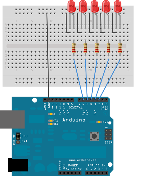
4. Sensor LDR.
5. Sensor LDR y encendido de LEDs.
Código:
/*
* http://www.geekfactory.mx
*
* Ejemplo de medidor de luz con Arduino utilizando una fotoresistencia LDR y
* un grupo de leds para mostrar el resultado de las lecturas. Este sketch puede
* servir como base para otros proyectos que requieren medicion de la intensidad
* de luz con una fotoresistencia.
*
* Mas detalles y la conexion completa para este sketch en:
* http://www.geekfactory.mx/tutoriales/tutoriales-arduino/tutorial-arduino-con-fotoresistencia-ldr/
*
*/
// Pin donde se conectan los leds
int pinLed1 = 2;
int pinLed2 = 3;
int pinLed3 = 4;
// Pin analogico de entrada para el LDR
int pinLDR = 0;
// Variable donde se almacena el valor del LDR
int valorLDR = 0;
void setup()
{
// Configuramos como salidas los pines donde se conectan los led
pinMode(pinLed1, OUTPUT);
pinMode(pinLed2, OUTPUT);
pinMode(pinLed3, OUTPUT);
// Configurar el puerto serial
Serial.begin(9600);
}
void loop()
{
// Apagar todos los leds siempre que se inicia el ciclo
digitalWrite(pinLed1, LOW);
digitalWrite(pinLed2, LOW);
digitalWrite(pinLed3, LOW);
// Guardamos el valor leido del ADC en una variable
// El valor leido por el ADC (voltaje) aumenta de manera directamente proporcional
// con respecto a la luz percibida por el LDR
valorLDR= analogRead(pinLDR);
// Devolver el valor leido a nuestro monitor serial en el IDE de Arduino
Serial.println(valorLDR);
// Encender los leds apropiados de acuerdo al valor de ADC
if(valorLDR > 256)
{
digitalWrite(pinLed1, HIGH);
}
if(valorLDR > 512)
{
digitalWrite(pinLed2, HIGH);
}
if(valorLDR > 768)
{
digitalWrite(pinLed3, HIGH);
}
// Esperar unos milisegundos antes de actualizar
delay(200);
}